Iec Vs Ansi Electrical Symbols - Practical Troubleshooting Of Electronic Circuits For Engineers And Technicians Eit Engineering Institute Of Technology Eit Engineering Institute Of Technology - Reposition them on the page and smartdraw will keep them.
Iec Vs Ansi Electrical Symbols - Practical Troubleshooting Of Electronic Circuits For Engineers And Technicians Eit Engineering Institute Of Technology Eit Engineering Institute Of Technology - Reposition them on the page and smartdraw will keep them.. Symbols of the most important equipment in transformer substation are given below. Electrical symbols are used to represent electrical and electronic devices in schematic diagrams. These basic electrical symbols are represented with their generic symbol. Ansi, iec & nema representation for or gate respectively. Add connecting lines and arrows.
This american national standard is a revision and expansion of american national standard graphic symbols for electrical and electronics symbols and buildups using symbols that have been recommended by the international electrotechnical commission are indicated by iec. It can be used for a zero potential reference point from where current is measured. Current transformers (cts) and potential. Ansi standards symbol iec standards electrical blocks. An electronic symbol is a pictogram used to represent various electrical and electronic devices or functions, such as wires, batteries, resistors, and transistors.
Schematic Design Methods Multiline Designs from multilinedesigns.com In the electrical engineering realm, this creates many complications. Ansi/iec symbols*iec 617 symbol iec codekm km ka ka kt kt kt kt sa sb sb sb sl sf sp st sq sq. Electrical symbols are the standard technique to represent an electrical circuit. The functions are supplemented by letters where amplification of the function is. A variety of specialized symbols originally used for aircraft applications have been added to make this. Complete circuit symbols of electronic components. There are several classes of accuracy for instrument transformers defined by the ieee, csa, iec, and ansi standards. American & european electrical symbols.
Ansi/iec symbols*iec 617 symbol iec codekm km ka ka kt kt kt kt sa sb sb sb sl sf sp st sq sq.
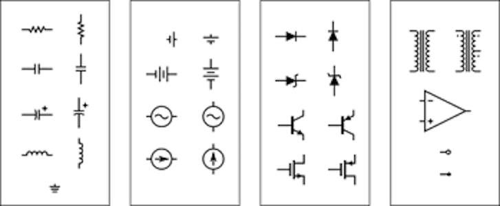
An electronic symbol is a pictogram used to represent various electrical and electronic devices or functions, such as wires, batteries, resistors, and transistors. Red3(electrical) 15 jul 04 11:09. American & european electrical symbols. Electrical symbols are used to represent electrical and electronic devices in schematic diagrams. Here below the cross reference of common schematic/wiring diagram symbols used throughout various parts of the world. Current transformers (cts) and potential. Symbols of the most important equipment in transformer substation are given below. The following tables describe the device and show the symbol by area of usage. These basic electrical symbols are represented with their generic symbol. Electrical symbols or electronic circuits are virtually represented by circuit diagrams. However, today most of the symbols. Click and stamp electrical symbols onto your layout. A ground symbol (iec symbol 5017) identifies a ground terminal.
Main electronic and electrical symbols that represent functions, components, devices and circuits in electronic and electrical schematic diagrams.they all belong to the most common and widely used standards in the world. It makes the graphical representation easier to work on and the users can also follow the different standards including, the ieee standard, iec (international electrotechnical commission), std., ansi, jic. More than 1500 electrical & electronic symbols of past and present. Click and stamp electrical symbols onto your layout. The symbols represent electrical and electronic components.
Electrical Stencil Iec Symbols 6nq880jvppnw from idoc.pub Reposition them on the page and smartdraw will keep them. Here below the cross reference of common schematic/wiring diagram symbols used throughout various parts of the world. The or gate performs the logical inclusive disjunction (true output for any true input)'.the output of or gate is logic high when any input is. There are two methods for indicating protection relay functions in common use. In the electrical engineering realm, this creates many complications. It can be used for a zero potential reference point from where current is measured. All circuit symbols are in standard format and can be used for drawing schematic circuit diagram and layout. Electrical symbols are used to represent electrical and electronic devices in schematic diagrams.
There are two types of instrument transformers:
There are two methods for indicating protection relay functions in common use. Electrical symbols and electronic circuit symbols are used for drawing schematic diagram. There are two types of instrument transformers: More than 1500 electrical & electronic symbols of past and present. Iec (din) vs nema (ieee/ansi). Add connecting lines and arrows. The following tables describe the device and show the symbol by area of usage. Main electronic and electrical symbols that represent functions, components, devices and circuits in electronic and electrical schematic diagrams.they all belong to the most common and widely used standards in the world. Electrical symbols are the standard technique to represent an electrical circuit. A ground symbol (iec symbol 5017) identifies a ground terminal. Current transformers (cts) and potential. Variable resistor / rheostat (ieee). Ansi, iec & nema representation for or gate respectively.
A ground symbol (iec symbol 5017) identifies a ground terminal. Ansi/iec symbols*iec 617 symbol iec codekm km ka ka kt kt kt kt sa sb sb sb sl sf sp st sq sq. It can be used for a zero potential reference point from where current is measured. Both are quite similar to each other although there are a number of differences. The symbols represent electrical and electronic components.
Electronics And Electrical Symbols Basics For Engineers from www.electronicsforu.com American national standard graphic symbols for electrical wiring and layout diagrams used in architecture and building construction. Reposition them on the page and smartdraw will keep them. Electrical symbols are used to represent electrical and electronic devices in schematic diagrams. Of these the iec and ansi/ieee standards for electronic symbols, i.e. There are some standard symbols to represent the components in a circuits. Iec (din) vs nema (ieee/ansi). This article gives some of the frequently used symbols for drawing the circuits. Current transformers (cts) and potential.
The symbols represent electrical and electronic components.
The autocad electrical symbol library includes bells, buzzers, horns, signal lights, capacitors, resistors, disconnects, fuses and circuit breakers along with pressure, limit, float and pull cord switches. Schemtic symbols are those that are most widely used. Iec codehl xs ka km km ka yv ec indicating light plug and socket control relay coil contactor coil motor starter coil timer coil solenoid coil. It makes the graphical representation easier to work on and the users can also follow the different standards including, the ieee standard, iec (international electrotechnical commission), std., ansi, jic. The or gate performs the logical inclusive disjunction (true output for any true input)'.the output of or gate is logic high when any input is. Reposition them on the page and smartdraw will keep them. Main electronic and electrical symbols that represent functions, components, devices and circuits in electronic and electrical schematic diagrams.they all belong to the most common and widely used standards in the world. This article gives some of the frequently used symbols for drawing the circuits. There are several classes of accuracy for instrument transformers defined by the ieee, csa, iec, and ansi standards. Ansi, iec & nema representation for or gate respectively. Ansi/iec symbols*iec 617 symbol iec codekm km ka ka kt kt kt kt sa sb sb sb sl sf sp st sq sq. Is there an easy way to take all the symbols already inserted in a schematic as ansi and convert them to iec? The functions are supplemented by letters where amplification of the function is.
This article gives some of the frequently used symbols for drawing the circuits iec. Iec specifically caters to electrical system design or electrical equipment quality requirement in the world.


.jpg)


0 Yorumlar